Telescopic guides are metal elements that extend outside the oven along with the baking sheet. Such runners make cooking easier and increase the safety of the process. However, there is no consensus on their benefits, and there are people who consider these components to be a redundant option. Let's figure out what these products are, what pros/cons they have, and consider the features of their installation.
Features of telescopic systems
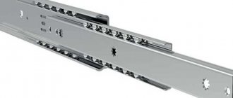
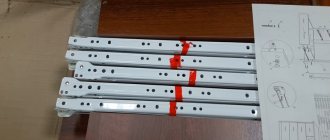
Ball guides have a fairly simple design; their mechanism consists of main and auxiliary parts - these are metal runners and balls, as well as stopper elements and other limiters, which can be metal or plastic.
Telescopic guides are technologically advanced, durable fittings
This system greatly simplifies the operation process.
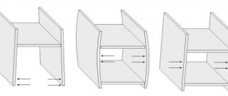
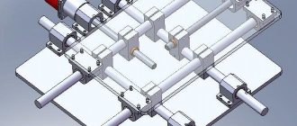
In order to understand the mechanism of their operation, we will consider the simplest version of two-section non-demountable telescopes. In this case, there are two rails that differ in size and are U-shaped, so that one part can fit into the other.
The mechanism is driven by moving metal tracks
There are small balls in the upper or lower part (between the parts), and the stopper is represented by the protruding edge of the rail. So in a certain area its movement stops.
The system received this name due to the fact that one track is placed inside another and extends like a telescope.
What types of ball guides are there?
Depending on the purpose, telescopic guides are distinguished by shape and other functions. Basically, they are divided according to the following characteristics:
- collapsible and non-dismountable mechanisms;
- two-section or multi-section (number of steps);
- multi-level or single-level.
The fittings have various mounting options
Telescopes can be installed both on the sides and in grooves
The difference between non-separable mechanisms is their rather low cost compared to analogues. This difference is due to some difficulties in the production of collapsible rails and a specific method of fixing the balls, because the structure must be designed in such a way that the guide can be disassembled without losing small elements.
Easy movement of boxes made of any materials is ensured by special balls
Of course, the cost is also influenced by the number of stages of the mechanism. This is also due to the peculiarities of the production of more complex parts.
Guides for this type of drawer come in a variety of colors, including black, steel, and zinc yellow. Balls are made of steel and nylon. It is worth noting that plastic balls are the quietest.
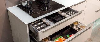
In most cases, drawers in cabinets with sliding doors are installed on telescopic guides
Attaching ball telescopic guides
On the outer side of the drawer, draw a horizontal line clearly in the center and screw half of the guide along it.
We recommend: We make plastic facades with aluminum edges
Then you need to draw the same horizontal line on the inner side of the chest of drawers.
You can accurately calculate the distances and parameters for fitting drawers into a chest of drawers using the drawings of the furniture product. To do this, we simply measure the appropriate distances from the bottom of the chest of drawers, at which we fix the second half of the guide.
After marking and securing all the guides, you can move the boxes into their places and consider the work complete.
Advantages and disadvantages of ball guides
Any mechanism has certain advantages and disadvantages. Such features should be taken into account before choosing one or another fitting for installation.
Table 1. Pros and cons of installing ball guides
| Advantages | Flaws |
|
|
Telescope mechanism suitable for massive iron boxes
The role of ball guides in furniture production
Despite the fact that ball guides are used in various industries, such fittings are most popular in furniture manufacturing.
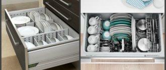
Most often they are installed in various wardrobe systems, chests of drawers, cabinets. This means that they can be found in any type of furniture that is designed for comfort and space saving. It is worth noting that the presence of such a system greatly simplifies the use of sliding cabinets.
A bed with drawers mounted on telescopic fittings
Prices for telescopic guides
Telescopic guides
How to calculate drawers for telescopic guides
Hello, friends.
In this article, we will learn how to determine the dimensions of drawers (with overlay facades), mark them and install them.
Initially, for the manufacture of boxes and drawers, 16mm thick chipboard will be used, and telescopic guides will be used for retractable fittings.
So, first, let's figure out how to calculate the sizes of the boxes.
Any such piece of furniture consists of four parts.
As a rule, two front parts are located between two side parts (to which the runners from the telescopic guides are then attached).
In order to calculate the dimensions of the front parts, we need to know the width of the entire box.
Let it be equal to S.
For calculations, we also need to know the clearances that need to be given on the telescopic guides. They are equal to 13mm (for each guide).
Now, based on the structure of the box itself, let’s calculate the size of its front part (Sfr):
Sfr = S-32-26-32 = S-90 (mm, all dimensions in the future will be in millimeters), where: 32 is the thickness of the two sides of the box, 26 is the tolerances for the guides on both sides (13+13=26 ), 32 – the thickness of the two side parts of the box.
The formula Sfr = S-90 can be used if, as mentioned above, the chipboard thickness is 16 mm.
If, for example, the chipboard thickness is 18mm, then:
Sfr = S-36-26-36 = S-98
The side parts of the drawer are usually equal to the dimensions of the guides themselves, which are:
250:300:350:400:450:500:50:600:650:700:750:800 (mm).
The most common option (for example, for the manufacture of kitchen sets - a box, 460 mm deep, for guides, 450 mm in size).
The height of the drawers depends on the height of the facades that must be installed on them.
For example, in our version, the upper facade will have a standard height of 140mm, and the height under it can be 100mm.
But for the other two facades, each 291mm high, this height can be taken, for example, 120, 150, 180.... In our case, it will be equal to 200mm.
Now, a rather important moment is marking the sides of the box for installing “telescopes”.
The markings must be correct, since the drawers must be located inside the box at a certain distance from each other. All this is “tied” to the position of the facades and the gaps between them.
So how do you make this markup?
First, you need to decide on the position of the facade relative to the drawer.
In the case of the upper facade, it will be located strictly along the central axis of the drawer.
The gaps between the drawer parts and the outer edges of the facade (in height) will be 20mm (top and bottom).
The remaining two facades will be positioned so that the distance between the drawer parts and the bottom edge of the facade is equal to, for example, 25mm.
Why 25mm?
The fact is that the lowest facade will overlap the box (at the bottom) flush.
Since the lower horizon of the box is 16mm thick, there must still be a gap between this horizon and the drawer (so that the latter can move without catching this horizon).
That's why:
25-16=9 (mm). This will be the size of the gaps.
Even if in this calculation we include the thickness of the fiberboard (from which the bottom of the box will be made), the thickness of which, for example, will be equal to 3 mm, then:
9-3=6 (mm).
As you can see, there is a gap, everything will work.
And the last condition: For simplicity of calculations, that part of the telescopic guide that will be attached to the drawer will be attached strictly in its center.
So, the total height of the box is 730mm.
Facade sizes: 140mm and 291mm.
The upper gap between the facade and the frame is 4 mm, and the gaps between the facades are 2 mm.
We mark the side from the top down.
But in order to start making markings, you need to determine the position of the guide axis on the drawer with the front.
In the case of the upper facade, it will be equal to 70mm above and below.
In the case of the other two fronts, it is calculated as follows:
Since the gap between the front and the drawer (bottom) is 25mm, and half the height of the drawer itself (200mm) is 100mm, the distance from the bottom of the front to the central axis of the drawer will be equal to:
25+100=125mm.
Then the distance from the top edge of the facade to this central axis will be equal to:
291-125=166 (mm), where 291 is the height of the facade.
These two sizes will be enough for us.
So, we calculate the position of the upper guide (all dimensions will be in millimeters):
4+70=74, where 4 is the gap between the upper facade and the upper edge of the box.
74+70+2+166=312. This is the position of the axis under the second drawer.
312+125+2+166=605 – position of the axis under the third (lower) drawer.
To check the correctness of the calculation, you need to add to the last size (605mm) the distance from the central axis of the bottom box to the bottom of the facade (125mm), since this facade completely covers the box from below, and we should get the height of the entire box, which is 730mm.
We check:
605+125=730 (mm).
Everything is correct.
The calculation algorithm, I think, is clear.
I will end here.
Until next time.
Installation of telescopic guides
We will consider the option of mounting telescopes using the example of the lower part of a kitchen table with drawers.
Calculations
At the very beginning, we need to determine the length and types of guides that will be used during further installation.
The basis will be a table of standard dimensions: length 520 millimeters and height 720 millimeters
The first type is a two-row incomplete extension design, and in our case such a mechanism will not work. The second type is the four row full extension slides which are perfect for this desk.
Next, you will need to determine the length of the sidewall, in this case it is equal to 520 millimeters, the type of back wall of the invoice. Even if the design assumes the presence of an inset wall, a 500 mm guide will still fit. Therefore, in any case, it will be optimal to choose exactly this length, but the method of fixing the back wall must be taken into account.
All calculations must be carried out starting from the facades
In this case, we will have 3 facades of 140 millimeters each and 1 facade of 292 millimeters. Calculating the length of the facades is quite simple. You just need to know the height of the case, which in this case is 720 millimeters.
This can be calculated using the following example, in the end we got 712 millimeters, which we divided into four facades
It should be borne in mind that each manufacturer has its own standard range of parts and most often the changes relate specifically to the height of the facades.
In order to correctly place the markings on the sides of the structure, it is necessary to consider the location of the drawers
Now you need to figure out how to calculate these dimensions. In this case, it is necessary to take into account the value of the lower indentation, which is 17 millimeters. So, the distance from the floor to the first box will be 25 millimeters, now you should add the height of half of this box, in this case it is 50 millimeters. The result was 75 millimeters.
The next size can be obtained taking into account the height of the lower facade. Here you should add 2 millimeters for the gap and another half from the other box. This is based on the fact that the boxes are 100 millimeters high and are located in the central part of the narrow facades, which are 140 millimeters high. Thus, 140 should be divided by 2 - it turns out 70 millimeters, which we add.
The next two calculations can be obtained by adding the previous ones
This means that 142 millimeters will need to be added to the dimensions that we have already received. Most often, the guides are installed before assembling the case itself, so you can simply subtract 16 millimeters from previous calculations or determine the values along the entire chain.
Next we will look at how to calculate the width of the drawers. In this case, our table length is 600 millimeters. Since in most cases laminated chipboard or MDF measuring 16 millimeters is used in furniture production, we will need to subtract 32 millimeters from the total width of the structure.
Determining the width of the drawers
In addition, from the resulting value of 568 millimeters, you will need to subtract another 26 millimeters for gaps.
Video - Installation of telescopic guides: calculations
Installation
Upon completion of all preliminary calculations, you can now move on to the practical part - installing telescopic guides.
The next two calculations can be obtained by adding the previous ones
Example of fixation on fiberboard
It is important to note one more digression - if you use guides on rollers, then the fiberboard bottom can be fixed to furniture nails. In the case of ball guides, it is recommended to use self-tapping screws as fasteners; in this case, you can also make an inset bottom.
Step-by-step instruction
Prices for cordless screwdrivers
Cordless screwdriver
Step one: the first thing we need to do is detach the inner part and attach it to the axle that divides our box into two parts. The guide has many holes for adjustment. In this case, we will start with longitudinal adjustment.
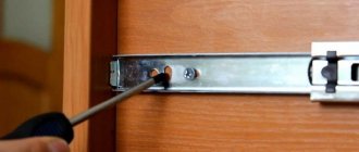
Attach the guide to the marking
Step two: you need to make a longitudinal adjustment so that the edge of the guide on the front is flush with the front edge of the side panel. After which you can already adjust the height.
Adjusting the location of the guide
Step three: after the work has been done, you need to begin installing the main part of the guide to the side of the table. Essentially, the mounting principle is the same, but in most cases there is no way to adjust the height. That is why when purchasing guides it is necessary to take this principle into account, because mechanisms with additional adjustment have a higher cost. Budget options were used here.
Installation of the main guide
Step four: the last step is to secure the drawers in place and check their functionality. You can insert all four drawers at once or one at a time.
Putting the boxes in place
Step five: the last step is to secure the facades. This should be done using double-sided adhesive tape and self-tapping screws (as shown in the image).
We install facades
There should be a gap of two millimeters between the facades. In order to make it, you should take a PVC edge tape of this diameter or any other object of the same width.
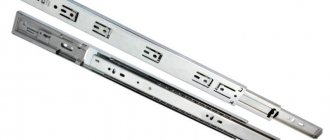
Full extension telescopic slides made of stainless steel
For one of my tasks, I needed full extension guides, these are used all the time in ordinary furniture, and of course I would just go and buy them in a store, especially since they cost about 2-5 dollars, but a problem arose. The fact is that I needed stainless steel guides, but more details in the review. Not long ago I posted a video about the completion of an apartment renovation epic, but then I said that not everything was actually finished, and one of this “everything” was a mirror in the bathroom. The problem of installing a mirror lasted probably a year and a half or two, but the solution came quite unexpectedly when I was cleaning out the furniture in the kitchen. Here I remembered a phrase from the film “Guest from the Future” - we need a push. I tried so many options for this, but I came up with such a simple one completely by accident.
Actually, that’s why I needed stainless steel guides, but unexpectedly it turned out that we either don’t have these on sale at all, or they cost some completely absurd amounts of money. To give you an idea, what I found cost from 60-70 to 100-300 dollars per set, sometimes made to order.
But when I went to Aliexpress, I was surprised again, not only are there simply a huge number of them on offer, but there is also a decent selection of sizes at much more affordable prices.
In the end I ordered it and it cost 12.88. The size is the smallest, 10 inches, in addition there is an option with and without a closer, I took without. because for my task it is not only not needed, but also inconvenient.
It took a long time, maybe they just got on sale. The order was placed on November 22, received in early January. Inside the package are two guides and a set of fasteners.
I didn’t even need fasteners, but I’ll tell you about the guides themselves and their use in more detail.
I think that those who came to read this review hardly need to explain what full extension ball guides are and how they differ from partial extension guides, ball and roller, especially since the answer is partially visible in the photo.
On the store page there are explanatory drawings that make it easier to select guides, with explanations in Russian!
One guide (there are two in the set) weighs almost a quarter of a kilogram, width 44mm, length when folded 250mm, when unfolded almost 500.
The thickness of the metal turned out to be difficult to measure, I got something around 0.8mm, the total thickness of the mechanism is almost 13mm, usually those that are sold here are about 12.7mm. A nuance was also discovered, there is a noticeable side play, i.e. if you press the extending part in one direction or the other, the thickness at the edges will vary in the range from 12.27 to 13.63. In this case, this is a necessary evil, since the length of the part with the balls is short, but in fact, if you use them for their intended purpose, i.e. for furniture, it will not be noticeable at all.
Regarding the thickness of the metal and the thickness of the guide itself, the store had completely different data. In my case, this was not critical at all, but still unpleasant.
But in general they move very smoothly, all moving parts are generously lubricated with viscous lubricant.
The latch is moderately soft. With conventional guides, due to the strong fixation, I sometimes had to slightly loosen the “fork” that is fixed to it, here I liked it better, it holds, but I didn’t have to bend anything.
A plastic retainer is installed at the end; in fact, there are no differences here from conventional guides
One of the linear bearings, cage and balls.
The balls themselves, of course, are very magnetic, but the material of the guides, although magnetic, is noticeably weaker. Of course, someone will write that stainless steel should be non-magnetic. A typical misconception, stainless steel can be different, both magnetic and non-magnetic, in this case something in between, an ordinary magnet almost does not feel it, but neodymium sticks.
As you understand, the length of the guides was not chosen “out of the blue”; I previously drew on a scale the place where they would need to be installed. To do this, I used the tile layout drawing that I made for this bathroom, then I placed furniture, a niche, a rod for the curtain, etc. on it, then, trying different options, I chose both the length of the guides and decided on the dimensions of the future mirror.
I ordered the mirror from the Kharkov company Apex-Mdf, which used to be called Apex-style. Compared to the general background, it turned out to be inexpensive, with a size of 480x780mm, something around 650 UAH (25 dollars), but it took a long time to make, perhaps because of the New Year holidays. The only thing that surprised me was that I didn’t need glass in aluminum, but a mirror.
Well, since this is a bathroom, it is therefore humid there and so that all this does not rust, the mirror was in a frame made of an aluminum profile. There were several options to choose from, I chose F1 as a compromise between reliability and aesthetics.
I was a little surprised when I noticed that the mirror was installed for a reason, but had a white protective film on the back. I hope this will increase its service life, since our regular mirror at home has already deteriorated due to moisture.
Based on the drawings and photographs of the installation site, I decided on the installation location of the guides on the mirror frame; it was lucky that the edge of the guide just fell on the inside of the frame plane.
The principle of installing a mirror is extremely simple; it must be hung on guides. Initially I wanted to somehow screw it to them, but there is a “nuance” here, I could screw it, I could even install it later, but since in this case the guide clamps would be behind the mirror, it would no longer be possible to remove it. Alternatively, it was possible to install the guides “inside out”. the narrow part on the wall, and the wide part on the mirror, but even so it’s not a fact that everything would work out.
Therefore, I started by preparing the grooves for hanging. In order not to break the mirror, I first removed the top part, drew it, marked the locations of possible holes, and at the same time noted where the steel corner ends so as not to get caught in it.
The result is such grooves. As an option, it was possible to buy steel canopies, but you have to look for them, and besides, it’s not a fact that I would be more comfortable with them. I cut the top rail from the bottom so that the guide would not stick up.
Initially, I planned to drill holes in the guides, cut an M4 thread and screw the screws in there, then take two M4 nuts and, at a distance of 2-3 mm from the plane, touch each other to create pins that would fit into the grooves of the mirror frame. But since the most I could do was just drill it out, because of the thin metal the thread would have turned out weak, and I couldn’t make a stamp so that the metal would bend and the thread would be wider, so I had to “go the other way.”
I sharpened four M4 nuts on a grinder, and then screwed them onto the inserted screws, then a washer and a regular nut. I ground it so as not to drill out large holes, so 6.5mm was enough for me. Well, I used nuts to simplify things, although you could have taken some kind of tubes, but you have to look for them.
With the lower part, I did everything in approximately the same way, with the only difference that here the holes for the canopies were shifted upward, and for entry, a hole was drilled, rather than a groove being cut out. Unfortunately, a step drill couldn’t fit here; I had to take a core drill with a diameter of 16 mm. As a result, not only did I use a bunch of tools, I also finished it off with a needle file 
It turned out quite neatly, but due to the large diameter of the crown, the hole turned out to be literally end-to-end, the same goes for the centering drill, in the end I had to remove it altogether later so as not to go right through.
The last stage of preparation, over which I also had to rack my brains a little. To prevent the mirror from being accidentally removed from the awnings, it had to be secured somehow, not only securely, but also unnoticeably. The solution turned out to be elementary, screw in two screws from below; by the way, their length also took part in calculating the location of drilling holes in the floor hinge.
Everything is prepared and ready to be sent to the installation site.
And here is the place for the future installation, the whole problem was that it turned out to be a very bad place to install the mirror. The door of the niche for pipes cannot be moved, just like the niche itself, the same applies to the washbasin. If the door were to the right, then the mirror could be hung on the wall, if to the left, then on the door itself, but “neither here nor there.”
Then everything is standard, marking, drilling, installing guides. The only thing I had to use was long plugs, 8x65, due to the fact that there is also gypsum board between the tiles and bricks (as far as I remember). Before installing the guides, I glued double-sided tape, it makes it easier to install them and thanks to it it is more difficult to split the tiles since it was screwed with decent force.
The guides are installed.
Then I installed the removable part with the canopy pins, I think now it’s clear why everything was done that way. By the way, in this form you can remove them without any problems, either using some kind of hook, squeezing the latch, or simply unscrewing the screws.
We hang a mirror and that’s it. The last operation even went unnoticed, I took the mirror and just hung it on the wall, it wasn’t even interesting, I didn’t have to adjust anything, file it, etc. After hanging it, I screwed in two screws from below and now you can remove the mirror only by first unscrewing them.
The installation height was selected so that the mirror would not interfere with anything, including the opening/closing of the washbasin valve, and, as usual, there would probably be something on the washbasin itself. The distance from the mirror to the tile was about 15mm, I was afraid that the gap would be very visible, but in practice it is almost invisible.
Now, to access meters and taps, it’s easy enough to roll the mirror to the left and open the door. When closing, the guides are held in place by latches and you cannot accidentally move the mirror.
At this point we can say that the penultimate stage is over, perhaps it turned out not as aesthetically pleasing as we would like, some things should have been thought out from the beginning, but you can’t think of everything, alas. but now I have a solution to a similar problem, and perhaps it will be useful to someone.
The last stage remains, connecting the intercom, and here I am still “in the process”, although it would seem that there is nothing to do there. It turned out that everything is not so simple. What does an ordinary person do when he wants to connect an intercom? He calls the organization that services them and calls a specialist to draw up a contract and connect. But here everything turned out to be wrong. I found out the phone number of the organization that installed the entrance intercom, called, and after a while the master called me back. We talked and he explained that he had contacted the house manager and she said that in the original contract we did not pay for the installation of a floor switch for this apartment. Well, no, no, I say, count how much there is in there. I did the math, called back and announced the amount... about 70 dollars, of which about 30 for the switch and 40 for visiting and “programming” the switch. And I haven’t yet clarified whether this includes running the cable (12 meters) and the cable itself, apparently not.
Somehow I was a little upset by this amount and I went on the Internet to see what kind of switch it was, fortunately I am somewhat familiar with this area. It turned out that the usual BK-4MV manufactured by Vizit is used, and it costs not 30, but rather 20 dollars, i.e. and here they increased the price by one and a half. In general, when I went to hang the mirror, I simultaneously looked at what kind of switch it was, I had two options, the old 4MV or the new 4AV, which is distinguished by the presence of a jumper for connecting the terminal resistor along the video line and the ground wire. At the same time, the new version costs 22 dollars, the old version costs about 18, but they are no longer available. Having opened the shield, I saw what I thought, BK-4MV, one apartment out of four possible and out of six on the floor was connected. But in any case, I will have to install a separate switch. I asked the head of the house about installation without a “company”, she said that in this case the intercom is common house property, so I can easily buy the switch myself and invite another specialist, as well as install it myself.
Of course, I’m not greedy and usually prefer to pay, but somehow when they charge me an amount for “programming” a switch that is only half as much as it costs to install, for example, an air conditioner, and at the same time they charge one and a half prices on the switch itself, I’m a little I'm upset. Moreover, “programming” is extremely simple and is described in detail in the instructions in Russian. As a result, I agreed with a friend that we would install it together, he would run the cable, I would connect it and “program” it.
But first, I found a switch on the Internet; it cost about $22, but it was a newer version than the one installed. The difference is that the new one has a built-in video terminator connected by a jumper, as well as a wire for connecting to the building ground bus.
The kit included instructions and a set of jumpers, however, I read the instructions before purchasing. Along the way, I decided to troll a little, found the Visit case, but from a different device, and installed an adapter for a video intercom in it. Actually, there is nothing interesting in the switch, a microcontroller, a video amplifier.
In principle, it was possible to assemble a switch, since the principle of its operation is not very complicated, and in addition there is a circuit without the use of a microcontroller. But I decided that this would be too much, the economy should be economical.
Then, while my friend ran the cable, he connected everything. There were almost no problems, the intercom worked on the second try, but on the first try the polarity of the audio/control line was connected incorrectly. But an ambush emerged from the video: the monitor screen remained dark, although the signal itself was 100%, this was confirmed by a test with a tester and the subsequent connection of another monitor.
Just in case, I wrote my phone number on the switchboard, in case someone from this floor or the next needs help connecting.
I had to make a “call to a friend,” or rather to the company with which I work on video surveillance. I explained the problem, they called the dealer and he explained that they needed to switch the video standard. The bottom line is that the monitor is designed to work with both AHD cameras and regular ones. In general, I guessed about this myself, but there was no such item in the menu, or in the instructions either.
It turned out that the developers put this point in such a way that “you can’t figure it out without a bottle.” You need to select the required input, then press the intercom button, the brightness/contrast/saturation control menu will appear on the screen. In this menu you need to select R, the settings will be reset, the menu will go dark, but the monitor will switch to the next mode, there are three or four of them (AHD-N, AHD-P, CVBS-N, CVBS-P).
I chose the desired mode and everything worked as it should, the only thing I have a slight complaint about is that the approach camera has a 4:3 format, and the monitor is 16:9.
The process of installing and connecting the intercom was the last step in the repair, and although they say that the repair cannot be completed, I still finished it
That's all for me, I hope it was useful.
Repair of roller guides
Despite the fact that telescopic guides are considered the most durable compared to other options, in some cases failures occur. Of course, under such circumstances, you can replace the fittings, but it is still worth trying to repair it.
In this case, we will look at repairs using the example of full extension ball guides. The breakdown is that the plastic retainer has become unusable. It allows you to hold the box, thereby preventing it from jumping out of the rail.
Plastic retainer
Thin plastic can break during use, as happened in our case.
Of course, such a breakdown does not have any effect on the operation of the guide itself, but the box will not be fixed properly. Therefore, if you push it all the way, it will simply fly out. This, in turn, is unsafe because massive boxes can fall on your feet. That is why, if there is no stopper, they should not be pulled out.
Video - How to remove a drawer with ball guides
Telescopic guide repair instructions
Step one: you need to take a wire with a diameter of 2 millimeters. In this case, strong stainless steel wire is used, but you can use another one. At the same time, it should spring a little. In total, we will need to cut 9 centimeters from it (maybe a little longer or shorter) - this is the standard length of the clamp in any type of guide. The mechanism used here is 50 centimeters long, but it can be shorter.
Wire with a diameter of 2 millimeters
Step two: stepping back 1 centimeter, you need to make a bend at the end of the wire. Next, use a tape measure to measure another 2 centimeters from this bend and make another one.
The result should be something like this, which will now need to be bent in the opposite direction
Step three: now you should step back from the edge about 5 millimeters and bend it in the other direction. First, we get a small bevel, which will not be enough for a stopper, so we take another pliers. Next, we use two pliers to make the maximum bend.
Now we have a more durable clamp
Step four: you need to step back another 3 centimeters from this bend, and make another bend in the wire. The main thing is that all bends should be exclusively in the same plane, otherwise you will end up with a crooked latch that will not work properly.
Let's make a bend like this
Now, using pliers, you need to make such an eye at the end
Now you need to hammer in the latch using the same tool
Prices for pliers
Pliers
At this stage our fixative is ready. Compared to a plastic product, it will last for many years, and besides, it is quite easy to make it at home. If desired, you can prepare a wire of 10 centimeters - a long clamp will work more smoothly.
Calculation of drawer dimensions
To install the ball slides correctly, let's check that you have detailed the drawer itself correctly.
Width
According to the technological dimensions of furniture design, an assembled box without a front in width (between it and the side of the product) should have gaps of 13 mm on each side . This is exactly how much the thickness of the “telescope” will take on.
See the diagram for box dimensions:
Length
Dimensions of telescopic guides for retractable structures from 250 to 800 mm in increments of 50 mm: 250 mm, 300 mm, 350 mm, 400 mm, 450 mm, 500 mm, 550 mm, etc.
Ideally,
the depth of the drawer should be equal to the length of the guide . Also remember to leave at least a 10mm gap between the back of the dresser and the back of the drawer.
However, there are situations when it is necessary to deviate from this condition. For example, if the internal depth of a cabinet, cabinet or chest of drawers is not 500 mm, but slightly less, let’s say 495 mm. In this case, if we take a 500 mm box, it won’t fit, but if we make it smaller, 450 mm long, the arm won’t rise, because at the same time we lose 35 mm of usable space:
- 35 mm (loss) = 485 mm - 450 mm (rail length)
- 485 mm = 495 mm - 10 mm (distance between the back wall of the drawer and the chest itself)
In such situations, it is worth considering the option of a 495mm drawer with 450mm slides. Of course, it won't go all the way out due to the shorter guides, but that's not a big deal. But the capacity has become larger; during use, the housewives will appreciate this!
Height
The height is usually made based on the needs of the person who will use it. The height is usually 80-250 mm.
Roller guides: what are their features?
In order to understand why many furniture makers choose telescopic guides, it is necessary to familiarize yourself with the structure of roller fittings.
Such mechanisms became available to a wide mass of buyers back in the 90s, when the first imported accessories began to be sold. In most cases, the products were manufactured in China, so they were not always of ideal quality, but there were exceptions.
Just a couple of decades ago, such mechanisms were considered very popular. They were used for furniture of any type, including cabinets, chests of drawers, and computer desks.
They are in the form of two planks, one of which is fixed to the wall of the structure, and the other to the box itself. The connection between them is represented by plastic rollers, thanks to which movement occurs.
Roller mechanism
The following positive aspects of installing roller guides can be noted:
- they are also distinguished by good strength;
- it is not difficult to repair such a structure yourself;
- they can be installed without the help of a professional technician;
- Guides of this type are characterized by a low price.
Roller guides are still used in budget furniture today.
In addition, the following negative aspects of installing such accessories are noted:
- it is impossible to pull out the drawers to the very end, because there must be some space left to connect the two parts of the guides;
- If installed incorrectly, there is a high probability of rapid breakdown of the mechanism;
- such fittings will not be able to support a box that is too massive, because the plastic rollers will simply break due to such pressure;
- plastic rollers wear out after a while - this leads to the fact that the drawers begin to constantly jam;
- less aesthetic appearance compared to telescopes.
Roller guides
What other retractable mechanisms are there?
There are other drawer systems:
- Metaboxes. This is the name of the retractable mechanism, which is based on roller guides. The system assumes only partial extension to three-quarters of the entire length. Such a box should carry a load of no more than 20 kilograms.
- Tandems. The mechanism is an open type guide. The system provides partial extension and smooth operation. The advantage is that the box will be easy to dismantle without specialized tools.
- Tandemboxes. These are the most expensive guides. The kit contains components for installing fittings to the facade and rear wall. Such a system sometimes involves automatic opening of the drawer - all you need to do is press the front.
Drawer on Tandembox guides
How to install telescopic guides
If the purchased oven does not have a pull-out system, it can be purchased separately in specialized stores. To properly connect the runners to the frame, it is recommended to start installation from the rear part. The fastener must be inserted into the holes, rotated to its original position and make sure that the stoppers are facing upward at this time. Next, you need to smoothly move the runners towards the rear wall and lightly press the guides: you should hear a click confirming successful installation. After these operations, you need to make sure that the guides are located at the same level and that the runners do not lock when the sheet is pulled out. The last stage is to bake delicious food in the oven and test the acquired innovation in action.
24-04-2020
Let's sum it up
You should choose one or another type of retractable fittings based on the design features of the furniture and your personal preferences. At the same time, if you want to get a durable mechanism, then you should not save money on its purchase, because low-quality guides quickly jam and stop functioning. The best option today is a telescopic system, and the installation of such fittings can be done without the help of a specialist - you just need to have all the necessary tools and fasteners on hand.